


Fire Resisting Cable |
||||||||||
![]() Fire Resisting Cables
Fire Resisting Cables
300/500V Mica+LSZH Insulated, Non-sheathed Power Cables to BS EN 50525-3-41 (Single Core)
FFX100 05mZ-U/K (CU/MGT+LSZH 300/500V Class 1/5)
APPLICATION
The cables are mainly used in power stations, mass transit underground passenger systems, airports,
petrochemical plants, hotels, hospitals and high-rise buildings.
STANDARDS
Basic design adapted from BS EN 50525-3-41(formerly BS 7211)
FIRE PERFORMANCE
Circuit Integrity |
IEC 60331-21; BS 6387 |
Flame Retardance (Single vertical wire or cable test) |
IEC 60332-1-2; EN 60332-1-2 |
Halogen free |
IEC 60754-1; EN 50267-2-1 |
No Corrosive Gas Emission |
IEC60754-2; EN 50267-2-2 |
Minimum Smoke Emission |
IEC 61034-2; EN 61034-2 |
VOLTAGE RATING
300/500V
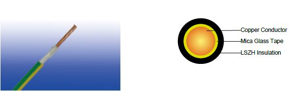
CABLE CONSTRUCTION
Conductor : Copper conductor according to BS EN 60228 class 1/5.
Fire Barrier : Mica glass tape.
Insulation : Crosslinked polyolefin material type EI 5 according to EN 50363-5.
Insulation Option : UV resistance, hydrocarbon resistance, oil resistance, anti-rodent and anti-termite properties
can be offered as option.
COLOUR CODE
Black, Blue, Brown, Grey, Orange, Pink, Red, Turquoise, Violet, White, Green and Yellow. Bi-colours of any
combination of the above mono-colours are permitted.
PHYSICAL AND THERMAL PROPERTIES
Maximum temperature range during operation : 90°C
Maximum short circuit temperature (5 Seconds) : 250°C
Minimum bending radius : 4 x Overall Diameter
CONSTRUCTION PARAMETERS
Conductor |
FFX100 05mZ-U/K |
||||
No. of Cores × Cross-sectional Area |
Conductor Class |
Nominal Insulation Thickness |
Min. Overall Diameter |
Max. Overall Diameter |
Approx. Weight |
No.×mm² |
|
mm |
mm |
mm |
kg/km |
1×0.5 |
1 |
0.6 |
2.9 |
3.4 |
13.5 |
1×0.75 |
1 |
0.6 |
3.1 |
3.6 |
16.5 |
1×1.0 |
1 |
0.6 |
3.2 |
3.8 |
19.7 |
1×0.5 |
5 |
0.6 |
3.1 |
3.6 |
14.2 |
1×0.75 |
5 |
0.6 |
3.2 |
3.8 |
17.7 |
1×1.0 |
5 |
0.6 |
3.4 |
3.9 |
20.7 |
ELECTRICAL PROPERTIES
Conductor operating temperature: 90°C
Ambient temperature: 30°C
Current-Carrying Capacities (Amp)
Conductor cross-sectional area |
Single-phase a.c. |
Three-phase a.c. |
mm² |
A |
A |
0.5 |
3 |
3 |
0.75 |
6 |
6 |
1.0 |
10 |
10 |
Note: These values apply to the majority of cases. further information should be sought in unusual cases eg.: |
||
Voltage Drop (Per Amp Per Meter)
Conductor cross-sectional area |
2 cables d.c. |
2 cables, single-phase a.c. |
3 or 4 cables, three-phase a.c. |
|||||
Ref. Methods A&B (enclosed in conduit or trunking) |
Ref. Methods C, F&G (clipped direct, on trays or in free air) |
Ref. Methods A&B (enclosed in conduit or trunking) |
Ref. Methods C, F&G (clipped direct, on trays or in free air) |
|||||
Cables touching |
Cables spaced* |
Cables touching, Trefoil |
Cables touching, flat |
Cables spaced*, flat |
||||
1 |
2 |
3 |
4 |
5 |
6 |
7 |
8 |
9 |
mm² |
mV/A/m |
mV/A/m |
mV/A/m |
mV/A/m |
mV/A/m |
mV/A/m |
mV/A/m |
mV/A/m |
0.5 |
101 |
101 |
101 |
101 |
87 |
87 |
87 |
87 |
0.75 |
68 |
68 |
68 |
68 |
59 |
59 |
59 |
59 |
1.0 |
50 |
50 |
50 |
50 |
44 |
44 |
44 |
44 |
Note: *Spacings larger than one cable diameter will result in a large voltage drop.